配置环境
https://soc.ustc.edu.cn/Digital/lab1/verilog_coding/
iverilog 编译器工具使用
https://zhuanlan.zhihu.com/p/95081329
要求:
- 代码实现功能
- 仿真波形
- testbeach
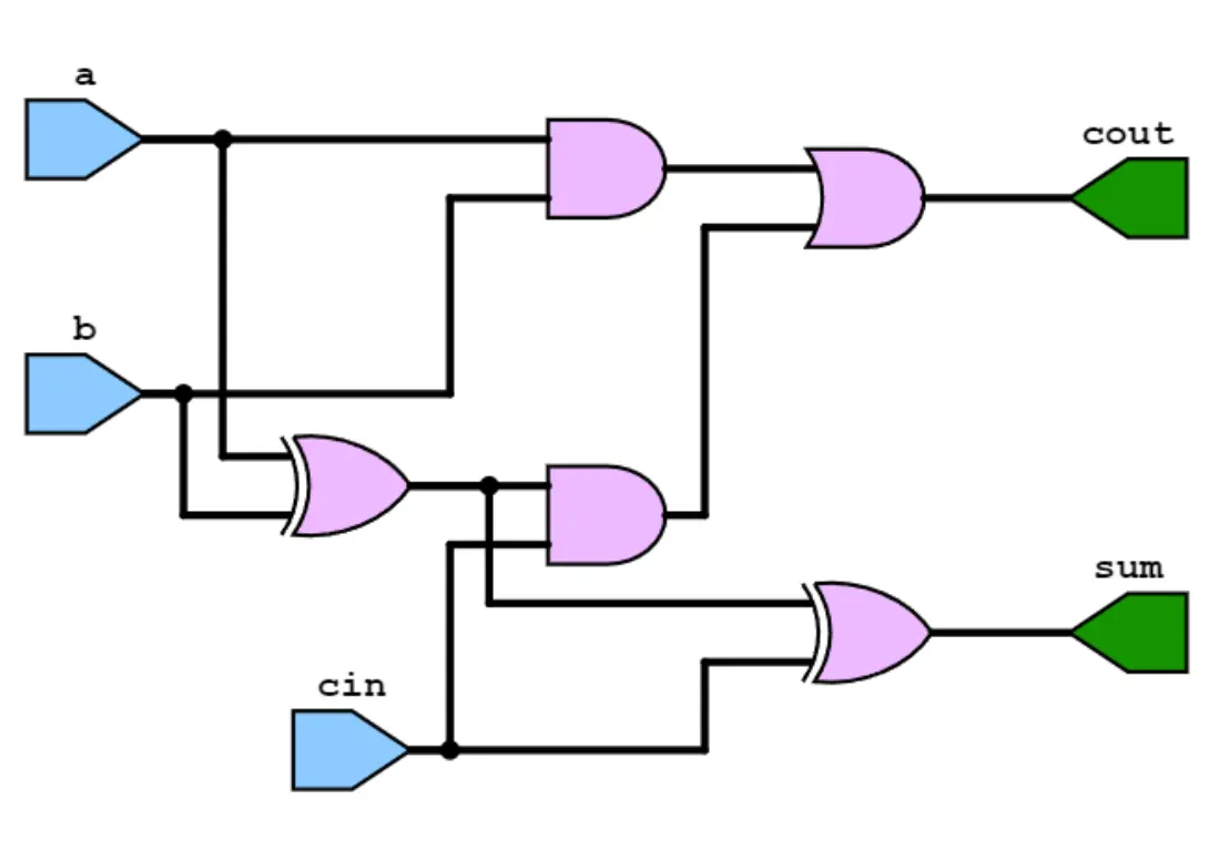
7.1 full adder
Implement the full adder of two 1-bit binary numbers in Verilog.
- Use the dataflow level description to implement the logic functions of both the sum and the carry for the higher-bit.
- Use the gate level description to implement the logic functions of both the sum and the carry for the higher-bit
第一问
adder.v
module fulladder(input a,      // 第一个1-bit输入
                 input b,      // 第二个1-bit输入
                 input cin,    // 进位输入
                 output sum,   // 和输出
                 output cout); // 进位输出

    // Dataflow level implementation for sum and carry
    assign sum  = a ^ b ^ cin; // 异或操作生成和
    assign cout = (a & b) | (b & cin) | (a & cin); // 与操作和或操作生成进位

endmodule
adder_tb.v
`timescale 1ns / 1ps  // 定义时间单位和时间精度

// Testbench without any inputs or outputs
module fulladder_tb();

    // Testbench内的信号声明
    reg a;    // 测试a输入
    reg b;    // 测试b输入
    reg cin;  // 测试进位输入cin
    wire sum; // 监测输出sum
    wire cout;// 监测输出cout

    // 实例化全加器模块
    fulladder uut (
    .a(a),
    .b(b),
    .cin(cin),
    .sum(sum),
    .cout(cout)
    );

	// 控制台输出判断正确性
    initial begin
        $monitor("now a = %d, b = %d, cin = %d, sum = %d, cout = %d\n"
        , a, b, cin, sum, cout);
    end

    // 测试例程
    initial begin
        // 初始化输入
        a = 0; b = 0; cin = 0;

        // 组合输入的所有可能性
        #10 a = 0; b = 0; cin = 1;
        #10 a = 0; b = 1; cin = 0;
        #10 a = 0; b = 1; cin = 1;
        #10 a = 1; b = 0; cin = 0;
        #10 a = 1; b = 0; cin = 1;
        #10 a = 1; b = 1; cin = 0;
        #10 a = 1; b = 1; cin = 1;
        #10; // 等待时间以观察最后的输出

        // 模拟结束
        $finish;
    end

    initial
    begin
        $dumpfile("wave.vcd");        //生成的vcd文件名称
        $dumpvars(0, fulladder_tb);    //tb模块名称
    end

endmodule
编译命令:
iverilog -o wave adder.v adder_tb.v
vvp -n wave -lxt2
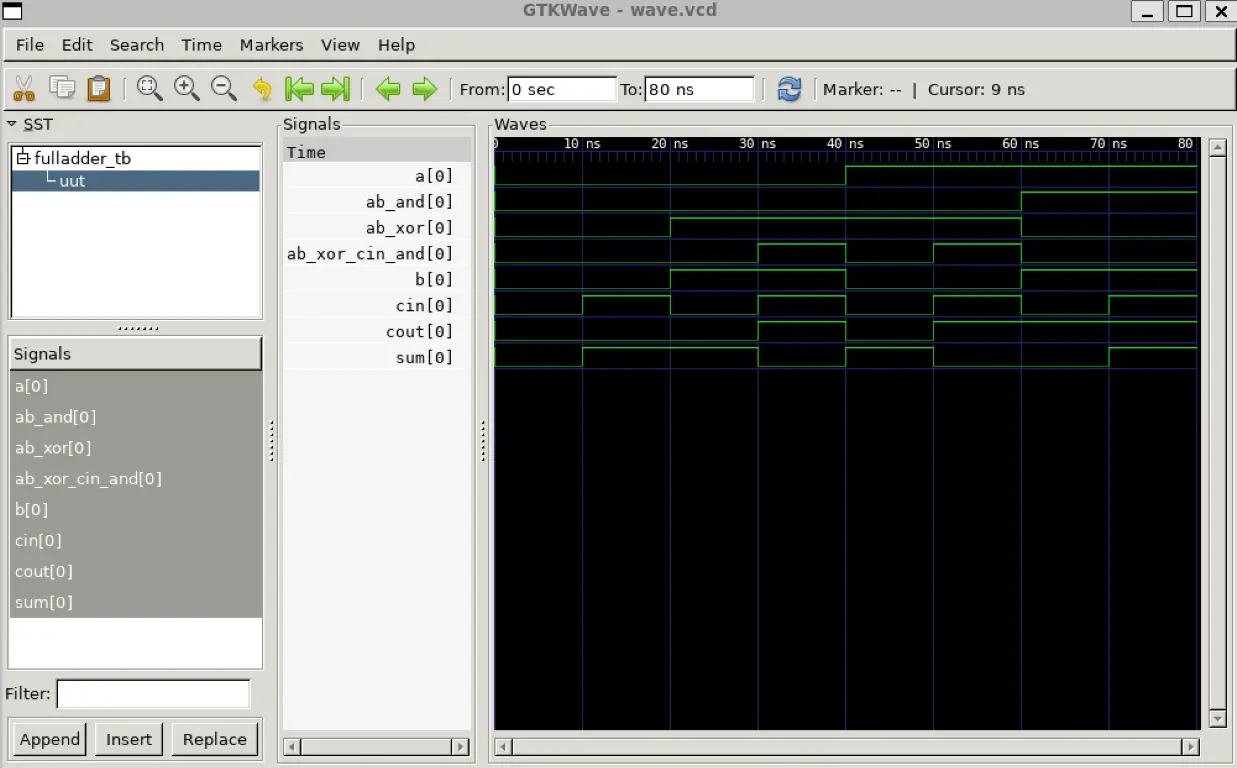
gtkwave wave.vcd
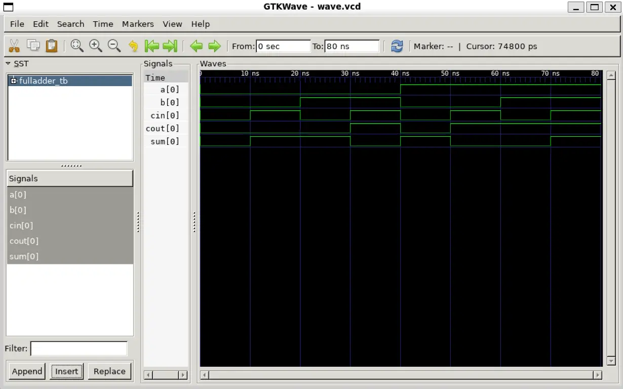
程序输出:
~/dev/verilog
❯ iverilog -o adder adder.v adder_tb.v

~/dev/verilog
❯ ./adder
now a = 0, b = 0, cin = 0, sum = 0, cout = 0

now a = 0, b = 0, cin = 1, sum = 1, cout = 0

now a = 0, b = 1, cin = 0, sum = 1, cout = 0

now a = 0, b = 1, cin = 1, sum = 0, cout = 1

now a = 1, b = 0, cin = 0, sum = 1, cout = 0

now a = 1, b = 0, cin = 1, sum = 0, cout = 1

now a = 1, b = 1, cin = 0, sum = 0, cout = 1

now a = 1, b = 1, cin = 1, sum = 1, cout = 1
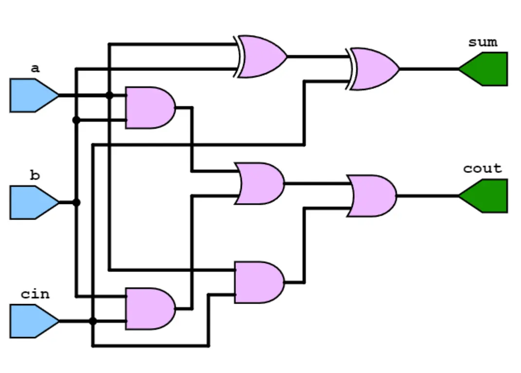
第二问
对 adder.v 修改:
module fulladder(
    input a,    // 第一个1-bit输入
    input b,    // 第二个1-bit输入
    input cin,  // 进位输入
    output sum, // 和输出
    output cout // 进位输出
);

  wire ab_xor;        // a和b的异或中间结果
  wire ab_and;        // a和b的与中间结果
  wire ab_xor_cin_xor;// ab_xor和cin的异或中间结果
  wire ab_xor_cin_and;// ab_xor和cin的与中间结果

  // Gate level implementation for sum and carry
  xor(ab_xor, a, b);               // a 异或 b
  and(ab_and, a, b);               // a 与 b
  xor(sum, ab_xor, cin);           // ab_xor 异或 cin
  and(ab_xor_cin_and, ab_xor, cin);// ab_xor 与 cin
  or(cout, ab_and, ab_xor_cin_and);// ab_and 或 ab_xor_cin_and

endmodule
编译命令不变,程序输出:
now a = 0, b = 0, cin = 0, sum = 0, cout = 0

now a = 0, b = 0, cin = 1, sum = 1, cout = 0

now a = 0, b = 1, cin = 0, sum = 1, cout = 0

now a = 0, b = 1, cin = 1, sum = 0, cout = 1

now a = 1, b = 0, cin = 0, sum = 1, cout = 0

now a = 1, b = 0, cin = 1, sum = 0, cout = 1

now a = 1, b = 1, cin = 0, sum = 0, cout = 1

now a = 1, b = 1, cin = 1, sum = 1, cout = 1
7.2 voting circuit
Implement the voting circuit of 7 people in Verilog.
- If more than 3 people agree, the decision is approved. Otherwise, the decision is rejected.
- Use the behavior level description to implement the logic function of the voting circuit.
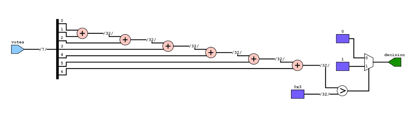
voting_circuit.v
// 定义投票电路模块
module voting_circuit(input wire [6:0] votes, // 7位输入,代表7个人的投票
                      output wire decision);  // 输出决定

// 实现投票逻辑:如果同意的人数超过3,则决定被批准
assign decision = (votes[0] + votes[1] + votes[2] + votes[3] + votes[4] + votes[5] + votes[6] > 3)? 1'b1 : 1'b0;

endmodule
voting_circuit_tb.v
module voting_circuit_tb;
    reg [6:0] votes; // 7位投票输入
    wire decision;   // 决定输出

    // 实例化投票电路模块
    voting_circuit vc(votes, decision);

    // 测试不同的投票情况
    initial begin
        // 测试所有人都不同意的情况
        votes = 7'b0000000; #10;
        $display("Votes: %b, Decision: %b", votes, decision);

        // 测试只有3人同意的情况
        votes = 7'b0011100; #10;
        $display("Votes: %b, Decision: %b", votes, decision);

        // 测试超过3人同意的情况
        votes = 7'b0111100; #10;
        $display("Votes: %b, Decision: %b", votes, decision);

        // 测试所有人都同意的情况
        votes = 7'b1111111; #10;
        $display("Votes: %b, Decision: %b", votes, decision);
    end

    initial
    begin
        $dumpfile("wave.vcd");        //生成的vcd文件名称
        $dumpvars(0, voting_circuit_tb);    //tb模块名称
    end
endmodule
编译命令:
iverilog -o wave voting_circuit.v voting_circuit_tb.v
vvp -n wave -lxt2
gtkwave wave.vcd
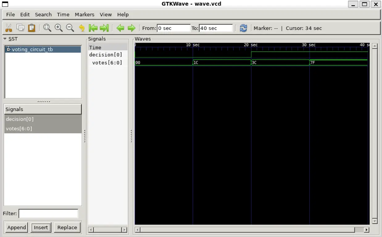
运行结果:
Votes: 0000000, Decision: 0
Votes: 0011100, Decision: 0
Votes: 0111100, Decision: 1
Votes: 1111111, Decision: 1